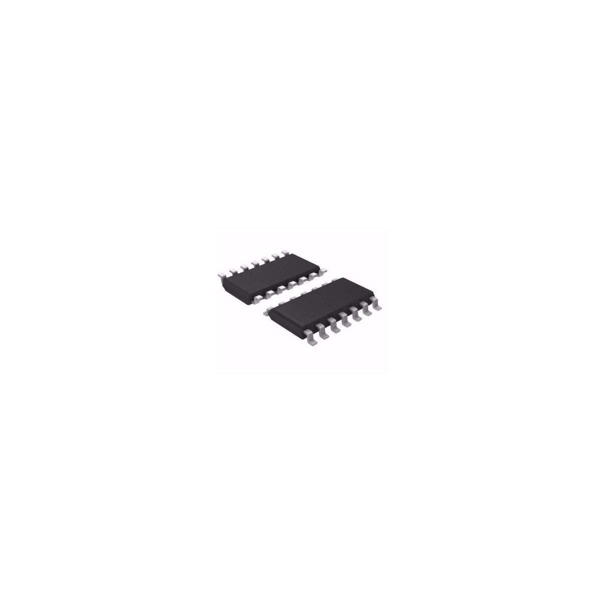
CD4051 8-Channel Analog Multiplexer/Demultiplexer
SKU: VNB3430
R7.00
No tax
Delivery: 2-5 working days
Delivery: 2-5 working days
CD4051 8-Channel Analog Multiplexer/Demultiplexer (SOIC 14)
PLEASE NOTE: We've moved our retail store - Click here for our new Address
Spend R2,000.00 more and get Free Shipping!
The CD4051 is a versatile CMOS analog multiplexer/demultiplexer designed to provide a simple and efficient solution for routing and selecting analog signals. This single 8-channel device can be used to connect one of eight inputs to a common output, or vice versa, making it ideal for a wide range of applications. The CD4051 is housed in a standard 14-pin Small Outline Integrated Circuit (SOIC) package, ensuring easy integration into various electronic circuits.
Key Features:
- Wide Range of Signal Levels: Supports digital signal levels from 3V to 20V and analog signal levels up to 20V peak-to-peak.
- Low ON Resistance: Typical ON resistance of 125Ω over a 15V signal input range.
- High OFF Resistance: Channel leakage of ±10pA (typical) at VDD – VEE = 18V.
- Logic-Level Conversion: Converts digital addressing signals of 3V to 20V to switch analog signals up to 20V peak-to-peak.
- Low Power Consumption: Very low quiescent power dissipation under all digital-control input and supply conditions.
- Break-Before-Make Switching: Eliminates channel overlap to ensure reliable operation.
Applications:
- Analog and digital multiplexing and demultiplexing
- Analog to digital and digital to analog conversion
- Signal gating
- Factory automation
- Televisions
- Appliances
- Consumer audio
- Programmable logic circuits
- Sensors
Pin Configuration:
- Pin 1 (CH 4): Channel 4 in/out
- Pin 2 (CH 6): Channel 6 in/out
- Pin 3 (COM): Common out/in
- Pin 4 (CH 7): Channel 7 in/out
- Pin 5 (CH 5): Channel 5 in/out
- Pin 6 (INH): Disables all channels
- Pin 7 (VEE): Negative power input
- Pin 8 (VSS): Ground
- Pin 9 (C): Channel select C
- Pin 10 (B): Channel select B
- Pin 11 (A): Channel select A
- Pin 12 (CH 3): Channel 3 in/out
- Pin 13 (CH 0): Channel 0 in/out
- Pin 14 (CH 1): Channel 1 in/out
- Pin 15 (CH 2): Channel 2 in/out
- Pin 16 (VDD): Positive power input
For more detailed information, you can refer to the CD4051 Datasheet.
YouTube Tutorials:
VNB3430
60 Items
No customer reviews for the moment.


