- On sale!

L298N Dual H Bridge Stepper Motor Driver Board with High current output and onboard 5V Regulator.
L298N Dual H Bridge Stepper Motor Driver Board with High current output and onboard 5V Regulator.
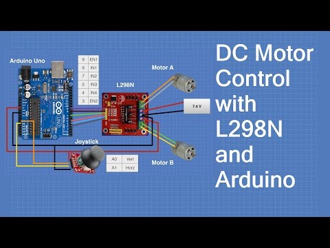
If you plan on working with robots or just building things that move you’ll eventually need to learn how to control a DC motor. The inexpensive L298N H-Bridge module is a simple way to achieve that. Coupling the L298N H-Bridge to a microcontroller like an Arduino will give you the ability to control both the speed and rotation direction of two DC motors.
In this article and it’s accompanying video I’ll show you everything you need to know to start adding some motion to your next Arduino project. So let’s get moving!
The first practical DC (Direct Current) motor was invented by the British scientist William Sturgeon in 1832. Since then DC motors have been part of countless pieces of equipment and machinery.
Today DC motors range from huge models used in industrial equipment to tiny devices that can fit in the palm of your hand. They are inexpensive and are ideal for use in your Robotics, Quadcopter, and Internet of Things projects.
Unlike LED’s you can’t just connect a DC motor to one of the output pins of your Arduino or Raspberry Pi and expect it to work. DC motors have current and voltage requirements that are beyond the capabilities of your microcontroller or microcomputer. It is necessary to use some external electronics to drive and control the motor, and you’ll probably need a separate power supply as well.
There are a number of ways to drive a DC motor from the output of your computing device. A single transistor can be used to drive a DC motor, this works well providing you do not need to change the direction that the motor is spinning.
A more versatile way of controlling a DC motor is to use a circuit called an “H-Bridge”. An “H-Bridge” is an arrangement of transistors that allow you to control both the direction and speed of the motor. Today we’ll examine a very common H-Bridge module based around the L298N integrated circuit.
In a simple DC motor there are two main components, the “stator” and the “armature”. The stator is a permanent magnet and provides a constant magnetic field. The armature, which is the rotating part, is a simple coil.
The armature is connected to a DC power source using a 2-piece ring installed around the motor shaft, these ring sections are called “commutator rings”. The two pieces of the commutator rings are connected to each end of the armature coil. Direct Current of a suitable voltage is applied to the commutator rings via two “brushes” that rub against the rings.
When DC is applied to the commutator rings it flows through the armature coil, producing a magnetic field. This field is attracted to the stator magnet (remember, opposite magnetic polarities attract, similar ones repel) and the motor shaft begins to spin.
The motor shaft rotates until it arrives at the junction between the two halves of the commutator. At that point the brushes come into contact with the other half of the commutator rings, reversing the polarity of the armature coil (or coils, most modern DC motors have several). This is great because at this point the motor shaft has rotated 180 degrees and the magnetic field polarities need to be reversed for the motor to continue rotating. This process repeats itself indefinitely until the current is removed from the armature coils.

The motor I have just described is referred to as a brushed DC motor because (obviously) it has brushes. Brushes, however, create many problems – they can start to wear over time, they rub against the motor shaft and they can even cause sparking as the motor gets older.
Better quality DC motors are the brushless variety. Brushless motors use a more complex arrangement of coils and do not require a commutator. The moving part of the motor is connected to the permanent magnet. Because they do not contain brushes these brushless motors will last longer and are also much quieter than brushed DC motors. Most quadcopter Motors are brushless motors.
DC motors are specified by the voltage level at which they operate. Common hobbyist motors run at 6 Volts or 12 volts DC.
To reverse the direction in which the DC motor rotates you simply reverse the polarity of the DC current that you apply to it. Changing the speed however, is a different story.
One method of changing the speed of a DC motor is to simply reduce its supply voltage. While this will work to some degree it is actually not a very good method of controlling motor speed as lowering the voltage will also lower the torque that the motor is capable of producing. Also, once the voltage drops below a certain point the motor will not rotate at all.
A far better method of controlling DC motors is to use pulse width modulation or PWM. If you’ve read up on controlling LEDs with your microcontroller you probably have already run into PWM as it’s also a good method of controlling the brightness of an LED.
With PWM the motor is sent a series of pulses. Each pulse is of the full voltage that the motor can handle so a 6-volt motor will be sent 6-volt pulses while a 12-volt motor will be sent 12 volt pulses. The width of the pulses are varied to control the motor speed, pulses with a narrow width will cause the motor to spin quite slowly. Increasing the pulse width will increase the speed of the motor, as illustrated below.

In order to stop the motor completely you just stop pulsing it, essentially sending it zero volts. To run it at full speed you send it the full voltage, again without pulsing it.

You can build a simple PWM generator using a 555 timer and discrete components but it’s a lot easier to use an Arduino. The Arduino has a function called “analogWrite” which is used to drive any of its PWM-capable outputs (the Arduino Uno has 6 digital outputs that are also capable of PWM).
Now that you know how DC motors work, how you can reverse their direction by changing polarity and how you can change their speed using pulse width modulation, let’s examine an easy way to do this using a very common circuit configuration called an “H-Bridge”.
An “H-Bridge” is simply an arrangement of switching the polarity of the voltage applied to a DC motor, thus controlling its direction of rotation. To visualize how this all works I’ll use some switches, although in real life an H-Bridge is usually built using transistors. Using transistors also allows you to control the motor speed with PWM, as described above.
In the first diagram we can see four switches which are all in the open or “off” position. In the center of the circuit is a DC motor. If you look at the circuit as it is drawn here you can distinctly see a letter “H”, with the motor attached in the center or “bridge” section – thus the term “H-Bridge”.

If we close (i.e. turn on) two of the switches you can see how the voltage is applied to the motor, causing it to turn clockwise.

Now we’ll open those switches and close the other two. As you can see this causes the polarity of the voltage applied to the motor to be reversed, resulting in our motor spinning counterclockwise.

This is pretty simple but effective. In fact if all you need to do is design a circuit to drive the motor full-speed in either direction you could actually build this as shown here, using a 4PDT (4 Pole Double-Throw) center-off switch. But of course we want to control the motor using an Arduino, so an electronic circuit where the switches are replaced by transistors is what we need.
While you can use discrete transistors to build an H-Bridge there are a number of advantages in using an integrated circuit. A number of H-Bridge motor driver IC’s are available and all of them work in pretty much the same fashion. One of the most popular is the L298N.
The L298N is a member of a family of IC’s that all have the designation “L298”. The difference between the family members is in the amount of current they can handle. The L298N can handle up to 3 amperes at 35 Volts DC, which is suitable for most hobby motors.
The L298N actually contains two complete H-Bridge circuits, so it is capable of driving a pair of DC motors. This makes it ideal for robotic projects, as most robots have either two or four powered wheels. The L298N can also be used to drive a single stepper motor, however we won’t cover that configuration in this article.
Here is a diagram of the pinouts of an L298N integrated circuit:

Although you can certainly purchase an L298N integrated circuit and wire it up yourself it is far easier to just buy a complete L298N circuit board, which is wired up and complete with connectors for motors, power supplies and input logic. These boards also have a 5 volt voltage regulator which can be used to supply the logic circuits. L298N driver boards are available from a number of sources like eBay or your local electronics shop at very reasonable prices.
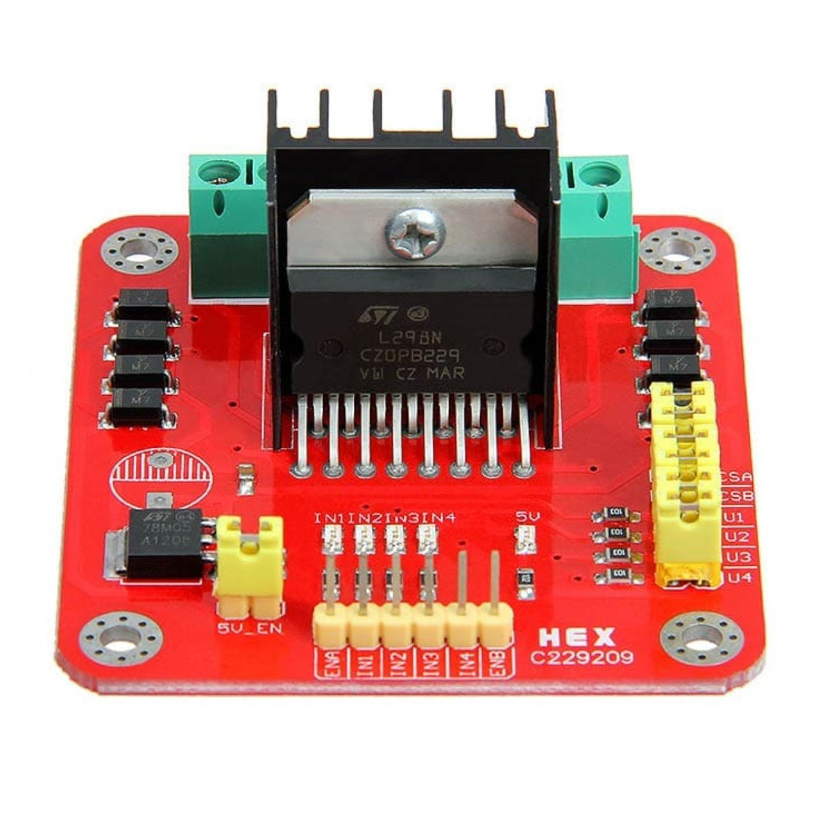
You’ll find a few different styles of L298N boards but they all operate in the same fashion. The board contains an L298N mounted on a heatsink, a 5 volt voltage regulator to “optionally) provide power for logic circuits, supporting diodes and capacitors and connectors as follows:
A typical L298N Board is shown here.

You’ll notice that the board also has a number of jumpers. Most of the time you will leave them in place, with the exception of one. They are as follows:
If you do use the internal voltage regulator you’ll have to supply the motor power supply with at least 7.5 volts.
Speaking of the motor power supply it needs to be a bit higher voltage than the actual motor requirements. This is due to the internal voltage drop in the transistors that form the H-Bridge circuit. The combined voltage drop is 1.4 volts, so if you are using 6 Volt motors you’ll need to give the board 7.4 volts, if you have 12 volt motors then your motor supply voltage will need to be 13.4 volts.
The board has four input terminals plus two enable terminals. You will use these terminals to control both direction and speed or each motor. They are as follows:
In order to simplify things a bit I’ll just discuss the inputs and enable for Motor A, Motor B functions identically.
The two Input lines control the direction that the motor rotates. I will call one direction “forward” and the other one “reverse”, if it makes more sense to you just substitute “clockwise” and “counterclockwise”.
You control motor direction by applying either a Logic 1 (5 Volts) or Logic 0 (Ground) to the inputs. This chart illustrates how this is done.
|
INPUT 1 |
INPUT 2 |
DIRECTION |
|
Ground (0) |
Ground (0) | Motor Off |
|
5 Volts (1) |
Ground (0) |
Forward |
|
Ground (0) |
5 Volts (1) |
Reverse |
| 5 Volts (1) | 5 Volts (1) |
Not Used |
As you can see only two combinations are actually used to control the direction of the motors rotation.
The Enable line can be used to turn the motor on, to turn it off and to control its speed. When the Enable line is at 5 Volts (1) the motor will be on. Grounding the Enable line (0) will turn the motor off.
To control the speed of the motor you apply a Pulse Width Modulation (PWM) signal to the Enable line. The shorter the pulse width, the slower the motor will spin.
We can use a solderless breadboard, a pair of motors and a few jumpers to test the L298N module.
You’ll also need a power supply for the motors. In my experiment I used a second power supply to supply the 5 Volts for the logic circuitry but you could use one supply for both the motors and logic if you wish. Just be sure to set the 5 Volt Jumper properly (if you use one supply it should be in place, if you use two like I did remove the jumper).
The initial hookup looks like this:

Note that both the motor and logic power supplies share a common ground. I’ve brought the 5 Volt supply with ground out to the solderless breadboard so it can be used to set logic levels.
To get things moving we will need to set the logic levels on the input and enable lines. In our first experiment we will set EN1, IN1 and IN3 to 5 Volts. The remaining inputs and enable line will be tied to ground.

This arrangement will cause Motor A to move in a forward direction. As the enable line for Motor B is at ground it will remain off.
Now let’s enable Motor B by setting EN2 to 5 Volts.

As you might expect this causes both motors to rotate in a forward direction.
Now we will change the inputs for Motor A, we will set IN1 to ground and IN2 to 5 Volts. The other connections will remain as they are.
If you understood the chart I showed you earlier with the input logic levels you won’t be surprised to see Motor A now moving in reverse. Motor B continues to move forward.
You can use this arrangement to experiment with controlling the motor direction, as well as enabling and disabling the two motors. But one thing that you can’t test this way is controlling motor speed. For this we will need to apply a PWM signal to the Enable lines. There are a number of ways of accomplishing this, for our next experiment we will do it using an Arduino.
Bringing an Arduino or similar microcontroller into the picture allows us to control both the direction and speed of each motor. I am going to show you how to do this using an Arduino Uno but you can also accomplish the same thing with a Mega, Nano or other Arduino compatible controller.
The Arduino Uno has 14 digital Input/Output (I/O) pins, six of which are capable of supplying a PWM signal.
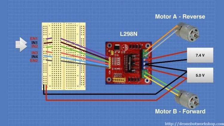
The following diagram shows how I have hooked up the Arduino Uno to the L298N board.

Note that the 5 Volts for the L298N board is now being supplied from the Arduino 5 Volt output. The Arduino itself is being powered via its USB cable, which of course will also allow you to load the sketch to make everything work. After the sketch is loaded you could remove the USB cable and power the Arduino with an external power supply (or a USB supply).
The input and enable lines in the L298N are driven from six Arduino digital output pins, as follows:
|
Arduino |
L298N |
|
9 |
EN1 |
|
8 |
IN1 |
|
7 |
IN2 |
|
5 |
IN3 |
|
4 |
IN4 |
| 3 |
EN2 |
I chose this pinout as Arduino output pins 9 and 3 are both capable of Pulse Width Modulation, if you wish you can use alternate pins. Just be sure to modify the sketch to reflect any pinout changes you make.
Speaking of the sketch, here it is:
|
1
2
3
4
5
6
7
8
9
10
11
12
13
14
15
|
No customer reviews for the moment.